|
<< Click to Display Table of Contents >> Entering Well Interval Data |
  
|
|
<< Click to Display Table of Contents >> Entering Well Interval Data |
|
Entering Well Interval Data
In ERPToolsX, WCI stores basic well completion information. WINT stores specific well interval or segment information and WMI stores routine well maintenance information. WCI and WINT are required tables for all newly established well locations.
WINT has been designed to capture the following attributes of each well segment: start/end depth, material composition, diameter, and where applicable screen slot size and percent open area. A well interval (screened interval) is defined by the sum of multiple well segments i.e.: (screen, blank casing, filter pack etc.). Segment type is synonymous with, and identified by the valid value entered in the field CLASS. The easiest way to conceptualize the mechanics of this table is to view the casing (and all components attached to it such as screen and foot) as one component, and all other materials serving to secure or seal the casing component in the borehole (e.g. grout, seal, and filter pack) as the other component. Within each component all depth entries must be contiguous. No overlap between depth entries is allowed within a component. Overlapping depth entries must occur between components for the well to function properly, but again no overlap can occur within a component. Note in the example below depth, screen no., class, and material are required for all segments. Segment diameter is supplied for the casing and screen only. Slot size and percent open area apply only to the screened segment. Validation will be performed on the values in this table alone and versus applicable depth and diameter fields in both LDI and WCI i.e.; borehole depth, borehole diameter, and total casing depth).
As mentioned previously, screen no. is assigned by the user to each screened or well interval. Its purpose is to define a logical screened interval for validation that can be treated as a single unit within a well. Validation proceeds to ensure that each component within a segment makes sense (spatial and logical): i.e. the seal IED can’t be greater than screen IBD, or screen IED can’t exceed TOTDEPTH or borehole depth). In the case of multiple screens, screen no. separates each interval, so that each segment is validated within its own interval, and intervals are compared to each other as a whole.
Additional screens that exist down hole are added and incremented after the preceding screen, (all components of the second screen for example have the screen no. 2 starting with the blank connected to the first screen). See example 2 below.
The Well Maintenance Information (WMI) table captures routine maintenance items such as protective cap replacement, ground surface elevation changes or measuring point elevation changes. When submitting elevation changes (ground surface or measuring point) both elevation and measuring point elevation must be supplied.
Example #1
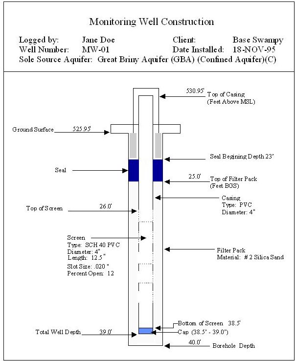

FIGURE B-4
LOCID |
IBDEPTH |
IEDEPTH |
CLASS |
SCRNO |
MATERIAL |
SDIAM |
SOUA |
PCTOPEN |
|---|---|---|---|---|---|---|---|---|
MW-01 |
0.00 |
23.00 |
GROUT |
1 |
CNC |
|
|
|
MW-01 |
0.00 |
26.00 |
BLANK |
1 |
PVC |
4.00 |
|
|
MW-01 |
23.00 |
25.00 |
SEAL |
1 |
BNT |
|
|
|
MW-01 |
25.00 |
40.00 |
FILPK |
1 |
FSP |
|
|
|
MW-01 |
26.00 |
38.50 |
SCRN |
1 |
PVC |
4.00 |
0.02 |
12 |
MW-01 |
38.50 |
39.00 |
FOOT |
1 |
PVC |
|
|
|
Example #2
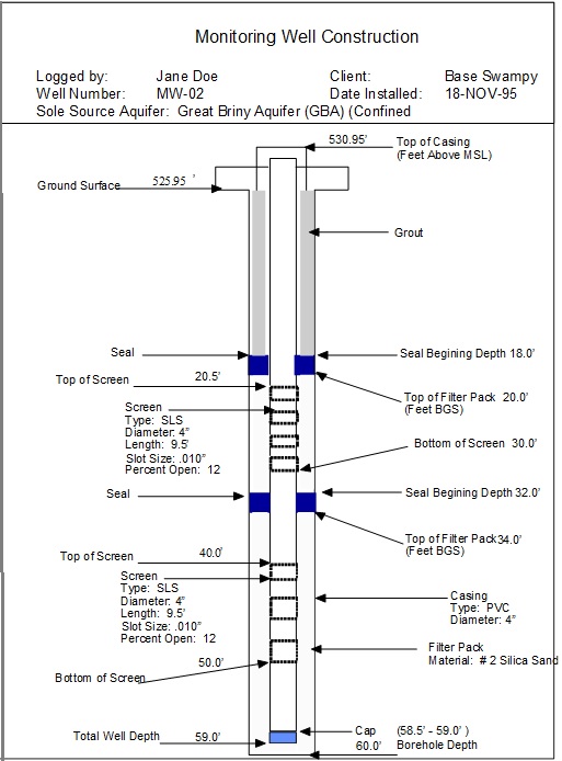

FIGURE B-5
LOCID |
IBDEPTH |
IEDEPTH |
CLASS |
SCRNO |
MATERIAL |
SDIAM |
SOUA |
PCTOPEN |
MW-02 |
0.00 |
18.00 |
GROUT |
1 |
CNC |
|
|
|
MW-02 |
0.00 |
20.50 |
BLANK |
1 |
PVC |
4 |
|
|
MW-02 |
18.00 |
20.00 |
SEAL |
1 |
BNT |
|
|
|
MW-02 |
20.00 |
32.00 |
FILPK |
1 |
FSP |
|
|
|
MW-02 |
20.50 |
30.00 |
SCRN |
1 |
SLS |
4 |
0.010 |
12 |
MW-02 |
30.00 |
40.00 |
BLANK |
2 |
PVC |
4 |
|
|
MW-02 |
32.00 |
34.00 |
SEAL |
2 |
BNT |
|
|
|
MW-02 |
34.00 |
60.00 |
FILPK |
2 |
FSP |
|
|
|
MW-02 |
40.00 |
50.00 |
SCRN |
2 |
SLS |
4 |
0.010 |
12 |
MW-02 |
50.00 |
58.5 |
BLANK |
3 |
PVC |
4 |
|
|
MW-02 |
58.50 |
59.00 |
FOOT |
3 |
PVC |
|
|
|
All photos contained in this online document are linked to full sided images of the imbedded image. Simply click on the image to have a browser view the image in its full size.