ABLOT |
See Ambient Blank Field Lot |
|
|
AF Base Code |
See AF Installation Identification |
|
|
AF Installation (AFIID) |
A code representing an installation, plant, or base from which Environmental data is collected. The AFIID code does not necessarily have to be an Air Force Base; it can be an Air National Guard Base, airport, Air Force Plant or other government installation. However, these coded values usually represent Air Force installations. (C5) |
|
|
Alternate Name (ALTNAME) |
Another name that is or has been used to label the site or location. This field should only be filled if the area delineated by the alternate name (alias) is an exact match for the area delineated by the identified ERPIMS identifier. (C15) |
|
|
Ambient Blank |
ASTM Type II Reagent Grade Water is poured at ambient (current) conditions into a sample container at a sampling site. The purpose of this blank is to detect sample contamination introduced during, or as a result of, field sampling activities. |
|
|
Ambient Blank Field Lot (ABLOT) |
This field is used in ERPTools to relate a lot of normal samples (collected in the field) to the related ambient blank. There will only be an entry for normal samples that are associated to an ambient blank. This field in the sample record for the ambient blank itself will be left blank. Entries in this field will be formatted as date and SAMPNO (DDMMYYNN) See Section 4.4, Field Lot Control Numbers, for further details. (C8) |
|
|
Ambient Conditions Blank |
See Ambient Blank |
|
|
Analysis Date (ANADATE) |
The date a sample or extract is analyzed in a laboratory. (D) |
|
|
Analysis Time (ANATIME) |
The time of day (24-hour clock) that a sample is analyzed in a laboratory. (N4) |
|
|
Analyte (PARLABEL) |
A code representing the analytical parameter for which an analysis was performed. (C12) |
|
|
Analyte Group Code (GROUPCODE) |
A code that identifies a group of environmental contaminants. This field will only be filled with an entry from its related Valid Value List. (C10) |
|
|
Analytic(al) Method (ANMCODE) |
Analytical method code is a coded value representing the method of analyses of a given parameter. (C7) |
|
|
Aquifer Base Depth (AQBASEDEPTH) |
The estimated water depth of an aquifer that is used to calculate certain hydrologic parameters. (N7,2) |
|
|
Aquifer Thickness |
See Saturated Aquifer Thickness |
|
|
ASTM Code (ASTMCODE) |
A 2 or 4 character code used in the ASTM classification of unconsolidated deposits. Deposits having characteristics of two lithologic groups are designated by a combination of the two character ASTM symbols. The predominant group is entered as the second 2-character code. For example, if the lithologic description is silty sand with clay, the ASTM Code should be "CLSC" with SC being the dominant lithology. If the material is composed of a single group, then only one 2 character code should be entered. If the layer consists of consolidated material, use the code "NACM" for the ASTM code and enter the appropriate LITHCODE in the Lithology Code field. (C4) |
|
|
Base Code |
See AF Installation |
|
|
Base Name |
See AF Installation |
|
|
Basis (BASIS) |
Identifies the basis (W = wet, D = dry or X = not applicable) on which analytical results are reported for all matrices. The basis for water, air, QC and gas samples is X while the basis for tissue and soil samples may be W or D. (C1) |
|
|
Bed Name (BEDNAME) |
The name of the geological bed to which a given Stratigraphic Unit belongs. (C20) |
|
|
Begin(ning) Depth (BEGDEPTH) |
The upper depth (in feet below ground surface) of a lithologic stratum. (N7,2) |
|
|
Bore Hole Depth (DEPTH) |
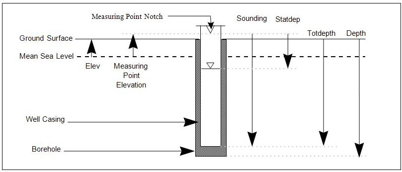
The total depth in feet of a bor ehole (including bore holes drilled to install wells) relative to the ground surface. (See Figure 3‑2: Measuring Point for Elevation, Figure 3‑3: Sample Well Composition Diagram, Figure 4‑4: Monitoring Well Construction Example #1, and Figure 4‑5: Monitoring Well Construction Example #2) (N6,2) |
|
|
Bore Hole Diameter (BHDIAM) |
The diameter of a bore hole in inches. (N4,2) |
|
|
Calculated Parameter Code (CALPARCODE) |
A code to identify which parameter has been derived from aquifer tests or tracer tests. (C5) |
|
|
Calibration Reference (CALREFID) |
A coded entry that links environmental and quality control (QC) samples to the corresponding calibration data. |
|
|
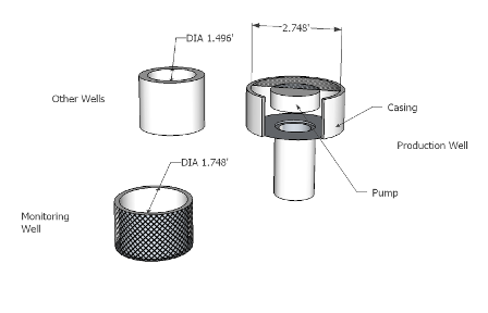
Casing Inside Diameter (CASDIAM) |
The inside diameter (in inches) of a casing. For monitor wells, the inside diameter of a screened casing interval should be used. For production wells, this is the inside diameter of the casing interval where the pump has been positioned. For all other wells, use the inside diameter of the casing. (N5,2)
|
|
|
Casing Material Code (CMACODE) |
A code describing the type of material used to make the casing for a well. (C3) |
|
|
Chain of Custody (COCID) |
Identifies the chain of custody report that describes the handling and transport of the sample. (C12) |
|
|
Changing Head Direction (HEADDIR) |
An indicator of the direction of change in water level related to slug and aquifer tests. Choices from the Valid Values List cover the following possibilities: Rising head, falling head, recovery, drawdown, or residual. (C3) |
|
|
Completion Method Code |
See Well Completion Method Code |
|
|
Confirming Value |
See VAL_CONFIRM |
|
|
i.Construction Method Code;(CMCCODE) |
A code indicating the type of equipment used to drill a bore hole or excavate a test pit (Drilling or Excavation Method). Enter "NA" for locations where construction was not done, e.g., surface water, sediments. (C2) |
|
|
Contract ID (CONTRACT_ID) |
The unique number assigned by the Air Force to a project after it has been contracted, but before the work begins. It is used to keep track of the work being performed. (C16) |
|
|
Cooler |
See Field Cooler ID |
|
|
Coordinate Type (CRDTYPE) |
The coordinate basis to which all coordinates are referenced at the installation. (C25) |
|
|
Coordinates East (ECOORD) |
The x-value (East-West) of the measured distance of a sampling or measuring location from the reference location of the know horizontal datum. |
|
|
Coordinates North (NCOORD) |
The y-value (North-South) of the measured distance of a sampling or measuring location from the reference location of the know horizontal datum. |
|
|
Cross Gradient |
A location is cross gradient of a site if it is adjacent to the flow path passing beneath the contaminant source. (See Figure 4‑6: Hydrogeological Gradient Example) |
|
|
Data Loading Handbook Version (HNDBKV) |
The version of the ERPIMS Data Loading Handbook followed during data entry via ERPToolsX. In practice, this refers to the version of validation software used. (C3) |
|
|
Data Quality Objectives (DQO) |
The DQO Process is a strategic planning approach based on the Scientific Method to prepare for a data collection activity accepted by the Department of Energy. It provides a systematic procedure for defining the criteria that a data collection design should satisfy, including when to collect samples, where to collect samples, the tolerable level of decision error for the study, and how many samples to collect, balancing risk and cost in an acceptable manner.
Using the DQO Process will assure that the type, quantity, and quality of environmental data used in decision making will be appropriate for the intended application, resulting in environmental decisions that are technically and scientifically sound and legally defensible. In addition, the DQO Process will guard against committing resources to data collection efforts that do not support a defensible decision. |
|
|
Date Established (ESTDATE) |
The date the construction of a sampled or measured location was completed. (D) |
|
|
Date of Test |
See Log Date |
|
|
Delivery Order (DO_ID) |
A number that is assigned to the Air Force form for "Orders for Supplies and Services." This sequentially assigned number is specific for a task under the contract number. (C4) |
|
|
Depth of Bore Hhole or Test Pit |
See Bore Hole Depth |
|
|
Detection Limit |
See Method Detection Limit (MDL) |
|
|
DL |
See Method Detection Limit (MDL) |
|
|
DO ID |
See Delivery Order |
|
|
DO Number |
See Delivery Order |
|
|
Downgradient |
A location is downgradient of a site if groundwater from the site will flow to the location. (See Fig B-6.) |
|
|
Drilling Company (DRLCODE) |
A code identifying the organization doing the drilling at a sampled location. For a location in which there was no drilling taking place, enter "NA" in this field. An example of this would be where a location had only surface water points sampled. (C4) |
|
|
Drilling/Excavation Method |
See Construction Method Code |
|
|
Dry |
Identification of a dry well. (C1) |
|
|
Dynamic measurements |
Measurements taken from a well that is undergoing current work such as pumping or purging. If dynamic measurements are taken, data fields for two depths (pumping level and recovery depth) as well as production rate and recovery time are to be completed. |
|
|
EBLOT |
See Equipment Blank Field Lot |
|
|
Elevation (ELEV) |
The elevation of the ground surface (for groundwater, soil or sediment sampling) or water surface (for surface water sampling) at a sampling location in feet above Mean Sea Level. (N7,2)
|
|
|
Ending Depth (ENDDEPTH) |
The lower depth (in feet below ground surface) of a lithologic stratum. (N7,2) |
|
|
EPA |
See EPA Data Qualifiers |
|
|
EPA Data Qualifiers (EPA_FLAGS) |
A field allowing the entry of established US EPA data qualifier codes not addressed by the Parameter Value Qualifier (PARVQ) codes. Data flag type and version are indicated by the valid value entered in the field DQTYPE. The use of flags defined by the contractor or laboratory is not allowed. All EPA_FLAGS entries are validated at the submission level, relative to analyte type, PARVAL, PARVQ and RL. (C6) |
|
|
Equipment Blank |
ASTM Type II Reagent Grade Water is poured over or through sample collection devices at a sampling site. The purpose of this blank is to verify the cleanliness of the sampling device(s). If multiple devices are used in sample collection, there can be an equipment blank produced for each device (e.g., bailer and pump). |
|
|
Equipment Blank Field Lot (EBLOT) |
This field is used, in ERPTools, to relate a lot of normal samples (collected in the field) to the related equipment blank(s). There will only be an entry for normal samples that are associated with a blank in the equipment field.. This field will be left blank in the sample record for the equipment blanks themselves. Entries in this field will be formatted as date and SAMPNO (DDMMYYNN) See Section 4.4, Field Lot Control Numbers, for further details. (C8) |
|
|
Equipment Rinsate |
See Equipment Blank |
|
|
ERPIMS |
The acronym for the Environmental Resources Program Information Management System. |
|
|
Establishing Company (ESCCODE) |
A code identifying the organization that establishes a sampling or measuring location. This company is generally the prime contractor. (C4) |
|
|
Excavating Company Code (EXCCODE) |
A code used only when a test pit is being established at a sampled or monitored location and is usually a different company from the drilling and establishing companies. For locations that have not been excavated, "NA" is entered. (C4) |
|
|
Expected (EXPECTED) |
The target result for a quality control sample or surrogate spike. An entry is required in this field for all samples having a SACODE other than "N." For normal environmental samples, a value is required for surrogates only. (See Tables in Sections 4.2, Field Sample Types and 4.3, Laboratory Sample Types) (N14,4) |
|
|
Extraction Date (EXTDATE) |
The date a sample is extracted or prepared for analysis. (D) |
|
|
Ex(traction) Method Code (EXMCODE) |
A code indicating the method that was used to extract or prepare a sample for analysis. (See Section 4.6, Analytical Method, Extraction Method, and Leachate Method Codes) (C7) |
|
|
Extraction Time (EXTTIME) |
The time of day, 24-hour clock, a sample was extracted or prepared. (C4) |
|
|
Field Blank |
See Ambient Blank. |
|
|
Field Cooler ID (COOLER) |
This field is used to identify the cooler that was used to transport a group of samples. This information can be used to determine if anomalous results can be attributed to contamination introduced during transportation. (C2) |
|
|
Field Lot Control Number |
See Lot Control Number. |
|
|
Field Tests |
Tests done in the field (e.g., pH, conductivity, specific gravity, etc.) |
|
|
Filter Pack Length (FPL) |
The length (in feet) from the bottom of the seal to the end of the filter pack, usually the end of the bore hole. Filter pack length (FPL) = bore hole depth (DEPTH) - seal end depth (SEDEPTH). (See Fig 3.3.) (N5,2)
|
|
|
Formation (FORMATION) |
This field captures the name assigned to the geological formation to which a given Stratigraphic Unit belongs. (C20) |
|
|
Fluid Type Code |
See Liquid Type Code |
|
|
Geohydrologic Completion Zone (GZCCODE) |
A code providing a general description of the water-bearing zone where the well has been screened. (C1) |
|
|
Geohydrologic Flow Classification Code (GFCCODE) |
A code that classifies and describes the flow of water in relation to the location and site. There can be more than one GFCCODE assigned to a location, but the data must be entered as separate records. For example, a location may be downgradient of one site and upgradient of another site. This information is usually taken from groundwater elevation and flow direction maps. Please note that the valid values for GFCCODE differ between data submission tools, and may not be interchanged. For further details, see Section 4.14, Entering SLI/SLX Data. (C1) |
|
|
Ground Surface Elevation |
See Elevation |
|
|
Groundwater Type |
Indicates STATIC or DYNAMIC well measurement. (C7) |
|
|
Group Code |
See Analyte Group Code |
|
|
Group Name (GRPNAME) |
The name of the geologic group to which a given Stratigraphic Unit belongs. See also: Bed Name, Member Name, and Formation Name (C20) |
|
|
Head Direction |
See Changing Head Direction |
|
|
Hydrostratigraphic Unit (HS_UNIT) |
This field holds the name for a Hydrostratigraphic Unit that is entered into the ERPIMS database. A Hydrostratigraphic Unit is defined as a body of rock or soil that contains related and characterized groundwater systems. In contrast, a Stratigraphic Unit is defined solely by the rock and/or soil that makes-up its composition. (C25) |
|
|
Initial Depth (STATDEP) |
The first measurement of a well's water depth under dynamic conditions (pumping or purging of a well). (N7,2) |
|
|
Installation Date (INSDATE) |
The date the well casing was installed. (D) |
|
|
Lab QC Lot Number (LABLOTCTL) |
A number identifying an autonomous batch or group of environmental samples analyzed together sharing the same quality control within the same time period. This grouping is equivalent to the EPA SW-846 concept of an "Analytical Batch." Field tests do not require an entry in this field. (See Section 4.5, Laboratory Lot Control Numbers) (C10) |
|
|
Lab Sample ID (LABSAMPID) |
The identification number assigned to a sample by the laboratory doing the testing. When a field test was performed, users should leave the field blank. (C12) |
|
|
Laboratory (LABCODE) |
A code identifying the analytical laboratory that performed the analysis of a sample(s). When a field test was performed, enter "FLD." (C4) |
|
|
Leachate Lot (LCHLOT) |
This field is used in ERPTools to identify a group of analytical samples that were prepared (together in a single batch) for testing by leaching from an environmental sample. LCHLOT is also used to preserve the relationship between the analytical samples, the (original) environmental sample, and any quality control samples that are associated. (C10) |
|
|
Leachate Method (LCHMETH) |
This field is used to record the method, chosen from the Valid Values List that was used for preparation (by leaching) of environmental samples. (C7) |
|
|
Liquid Type Code (FTCODE) |
This field is used to record the coded VVL value that corresponds to the nature of the liquid that was encountered in a well. Normally, this liquid will be groundwater. If another kind of liquid (free product for instance) is encountered, this field shall so note and this should be explained in the Remarks field of the Groundwater Level Table. (C1) |
|
|
Lithology Code (LITHCODE) |
A LITHCODE is a coded value describing the lithology of both consolidated and unconsolidated materials on the basis of such characteristics as color, mineralogical composition and grain size. (C4) |
|
|
Location Classification Code (LTCCODE) |
A code describing the type of location that is undergoing sampling. Examples of LTCCODE are: BH -bore hole, WL -well, CH -channel/ditch, etc. (C2) |
|
|
Location Description (LOCDESC) |
An area where text can be entered concerning any additional information describing a sampled location. This location description primarily gives information on the actual location of a well/bore hole. (C240) |
|
|
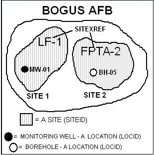
Location Identification (LOCID) |
This is a unique identifier assigned to a specific point (location) where measurements or samples are taken. (See Figure 3‑4: Sites vs. Locations Diagram) Once assigned, Location Identification must be consistent from one environmental investigation to another. When a location is initially established as a bore hole and later completed as a monitoring well, only one LDI record is required.
Existing Location Identifications shall be obtained by contacting the ERPIMS Help Desk. The LOCID field for quality control samples is not used to reflect a geographic location, instead the field designates whether the QC sample is a field QC (FIELDQC) or a laboratory QC (LABQC). When entering LOCIDs, the format shall follow the following naming convention: the first two positions of the LOCID shall refer to a valid location type (LTCCODE). The third position may contain a hyphen (-). This is the only special character that is allowed in LOCID. The fourth and fifth position shall contain numbers. Do not use spaces (e.g., enter MW01 or MW-01 not MW 01).
Background locations shall be submitted like any normal location. If the location is newly established, indicate that the location was selected for background sampling in the remarks field of the LDI file. If the location is not located within an official site, it is not necessary to enter a site identifier in the LDI file. (Note: you will receive a warning if this field is left blank.) The user shall include a statement in the transmittal letter to indicate that the field was left blank because the location served as a background check, and it is not associated with a site. Regardless, whether a sampling location is new or old, an entry shall be made in the BCHSLI file, with the GFCCODE “B,” indicating that it is being utilized as a background location for the site to which it pertains. See also 4.14, Entering SLI/SLX Data. (C10) |
|
|
Location Proximity Classification Code (LPRCODE) |
A code indicating the proximity of a sampled location to the applicable installation's boundaries. There are only two codes for LPRCODE: I - inside installation's boundaries and O - outside installation's boundaries. Do not enter 1 (one) or 0 (zero). (C1) |
|
|
Location Type Classification Code |
See Location Classification Code |
|
|
LOCID |
See Location Identification |
|
|
Log Code (LOGCODE) |
A code identifying the company collecting the samples or performing field tests. (C4) |
|
|
Log Date (LOGDATE) |
This is the date the logging of a bore hole or a pit is performed (lithologic description information), the date a test is performed (calculated hydrologic parameter information), the date a measurement is taken (groundwater level data) or the date a sample is collected, field test performed or a field quality control sample generated (environmental sampling information, sample/test/result information). (D) |
|
|
Log Time (LOGTIME) |
The time a measurement is taken (groundwater level data) or sample is collected, a field test performed, or a field quality control sample is generated (environmental sampling information). This information must be provided if more than one test is done on a single well on the same day. If this does not occur, enter four zeros (0000). Note that LOGTIMES must be consistent between Normal samples (N) and any associated QC samples (e.g., MS, FD, SD, LR). (C4) |
|
|
Logging Company Code (LOGCODE) |
A code identifying the logging company responsible for the logging or testing of a bore hole or a pit (lithologic description information), the taking of a measurement (groundwater level data), the collection of samples or the performing of field tests (environmental sampling information). This company is usually the same as the establishing company (ESCCODE). (C4) |
|
|
Lot Control Number (LOTCTLNUM) |
A coded value that signifies a set of samples which link a group or batch of environmental samples and their corresponding field quality control samples. Sometimes referred to as Field Lot Control Number. (See Section 4.4, Field Lot Control Numbers, and 4.5, Laboratory Lot Control Numbers) (C5) |
|
|
Lot Control |
See Lot Control Number |
|
|
Matrix (MATRIX ) |
Coded value identifying the sample medium collected for analysis, e.g., soil, water, air, etc. For QC blanks and reference materials, use the codes WQ, SQ, and AQ as specified in the valid value list. Since QC replicates and matrix spikes are in effect the same as the original sample, use the actual matrix of the original sample (see Sections 4.2, Field Sample Types, and 4.3, Laboratory Sample Types). (C2) |
|
|
Measuring Point Elevation (MPELEV) |
The elevation (in feet above Mean Sea Level) of the measuring reference point used for measuring groundwater depth level measurements. Typically, this elevation is measured from the top of the notched well casing. (See Figure 3‑2: Measuring Point for Elevation, and Figure 3‑3: Sample Well Composition Diagram) (N7,2) |
|
|
Media (Media) |
A coded value, chosen from the Valid Values List, that indicates the type of material or sample medium that is being treated by a given Remediation Technology. (C1) |
|
|
Member Name (MBRNAME) |
This field captures the name of the geological member to which a given Stratigraphic Unit belongs. (C20) |
|
|
Method Detection Limit (MDL)
|
This field is used to report the smallest quantity of a given analyte that can be detected from a prepared sample using the indicated analytical method. MDLs are corrected for dilutions when performed. When reporting dilutions, the detection limit must be multiplied by the dilution factor in order to reflect accurately the detection limit for the diluted sample. The MDL field should be left blank for surrogate compounds, for most analytes reported in the units “PERCENT” and for measurements where detection limits are not applicable, (e.g., temperature, pH, specific conductance and turbidity.) See also: Reporting Limit (RL) and Practical Quantization Limit (PQL). (N14,4) |
|
|
Observation Well Location (OBS_LOCATION) |
This field is used to record the location (using the observation well’s LOCID) of the place where an observation is made for an aquifer test or a tracer test. Observation well water levels for aquifer tests are captured in the Observation Well Water Level table (OWL). Tracer material concentrations at observation wells are captured in the Tracer Observation Well table (TOW). NOTE: The LOCID field the in OWL and TOW tables must be filled with the location where the slug/tracer was injected. The OBS_LOCATION field in these tables specifies where the water level or tracer concentration was measured. |
|
|
Operable Unit Code (OUCODE) |
A two character code that is used to uniquely identify a specific Operable Unit. (C2) |
|
|
Parameter (PARAMETER) |
This field is used in the Remediation Technology Performance (RTP) and Remediation System Performance (RSP) tables to identify what aspect of system/technology performance is being monitored. (C5) |
|
|
Parameter Label (PARLABEL) |
A code identifying an individual parameter, compound or analyte analyzed. (C12) |
|
|
Parameter Value (PARVAL) |
This field represents the actual analytical value for a compound/analyte generated after a sample has been analyzed or a test performed. (N14,4) |
|
|
Parameter Value Qualifier (PARVQ) |
A code qualifying the analytical results (PARVAL). These codes are not the same as EPA or CLP qualifiers and are not designed to code for QC criteria failure. The qualifiers used must be ERPIMS qualifiers. Contact the ERPIMS Help Desk if clarification is needed. See Section 4.7, Parameter Value Qualifiers, for more details. (C2) |
|
|
Parameter Value Uncertainty (PARUN) |
The value that measures the uncertainty of the analytical test (expressed as + or - some value). It is established through the analysis of laboratory quality control samples associated with the normal environmental samples. (N12,4) |
|
|
Percent Open Area (PCTOPEN) |
The percent of the screened interval that is open. (N3,1) |
|
|
Practical Quantization Limit (PQL) |
PQL is defined as the lowest concentration that can be reliably measured within specified limits of precision and accuracy during routine operation. ERPToolsX captures the Reporting Limit (RL) which serves a purpose similar to that of PQL. Any PQL reported must be adjusted for dilutions. See also Reporting Limit (RL) and Method Detection Limit (MDL). |
|
|
Precision |
The number of digits to the right of the decimal point. Precision only applies to the PARVAL, PARUN, and EXPECTED fields. (N1) |
|
|
Production Rate (PRODRATE) |
The pumping/purging rate (in gallons/minute) at which a well is evacuated during groundwater level measurements. Used for the dynamic measurements taken during a pumping or purging of a well. (N6,1) |
|
|
Pump Depth (PUMPDEP) |
The lowest groundwater level depth measurement (in feet) during the pumping or purging of a well. The measurement is taken from the well's reference point (MPELEV). A dynamic measurement. (N7,2) |
|
|
QAPP Flags (QAPPFLAGS) |
Flag values are set in accordance with the AFCEC Quality Assurance Project Plan (QAPP). These are qualifiers assigned to analytical result data during validation and review. (C2) |
|
|
QC Type |
See Sample Type |
|
|
Radial Well Distance (WELLDIST) |
The distance, expressed in feet, between the observation well and the injection/test well. Note: This field will be added to the TOW and OWL tables in future revisions of ERPTools. |
|
|
Recovery Depth (DEPWAT) |
The measurement of water depth (in feet) after recovery from purging. This measurement is made from the reference point that is the elevation from the top of the casing where it is notched (MPELEV). (N7,2) |
|
|
Recovery Time (RECTIME) |
The elapsed time (in minutes) for a well's water level to stabilize or recover to a certain level after purging. This is a dynamic measurement. (N4) |
|
|
Remediation System |
A series of Remediation Technologies that work in concert that can be composed of a single or multiple remediation technologies. Table entries may also consist of groups of subsystems of remediation technologies. A Remediation System is made-up of one or more Remediation Technologies (or Remediation Units) that are used together to treat a particular area of contamination. Remediation Systems are sometimes referred to as Remediation Trains. |
|
|
Remediation System ID (RSID) |
A user defined name that is used to refer to a Remediation System that is maintained as part of the record for that Remediation System. |
|
|
Remediation System Stage (RSSTAGE) |
Coded value for the type of remediation system that is being used. (e.g., treat ability studies, field demonstrations, pilot studies, etc.) |
|
|
Remediation Technology |
Description of a discrete remediation activity. This is the information with regard to a particular piece of equipment that is used in the remedial action. The term Remediation Technology can also refer to a group of components that acts as a single unit cleanup apparatus. Thus, a Remediation Technology is sometimes referred to as a Remediation Unit. |
|
|
Remediation Technology Class (RTCLASS) |
A code that represents a particular classification of Remediation Technologies. (e.g., in-situ, ex-situ, or mixed) |
|
|
Remediation Technology ID (RTID) |
A user defined name that is used to refer to a Remediation Technology that is maintained as part of the record for that Remediation Technology. |
|
|
Remediation Technology Type (RTTYPE) |
A coded value that represents a particular type of Remediation Technology. (e.g., in-situ vitrification, bio-reactor, slurry wall, etc.) |
|
|
Remediation Train |
See Remediation System |
|
|
Remediation Unit |
See Remediation Technology |
|
|
Reporting Limit (RL) |
This field captures the reporting limit specified for the project. In the case of AFCEC contracts, this limit will either be specified in the AFCEC Quality Assurance Project Plan (QAPP) or will be an AFCEC approved project-specific reporting limit. RL is required for all ERPTools data submissions. Reported RLs must be adjusted for dilutions. See also: Method Detection Limit (MDL) and Practical Quantitation Limit (PQL). (N14,4) |
|
|
Result |
See Parameter Value |
|
|
Run Number (RUN_NUMBER) |
This field permits the numerical coding of multiple or repeat analyses of a sample by the same analytical method. For example, a sample extract is diluted and re-analyzed for analytes that exceeded calibration during the first run. Data from the first run are captured as RUN_NUMBER = 1 and from the second as RUN_NUMBER = 2. (N2) |
|
|
Sample Beginning Depth (SBD) |
The upper depth (in feet) from the ground surface or water surface at which a sample is collected. (N7,2) |
|
|
Sample Ending Depth (SED) |
The lower depth; (in feet) from the ground surface or water surface at which a sample is collected. (N7,2) |
|
|
Sample Matrix |
See Matrix |
|
|
Sampling Method Code (SMCODE) |
A code identifying the method of sampling used to collect a sample. For QC blanks or other samples where sampling method is not applicable, enter "NA." (C2) |
|
|
Sample QC Type |
See Sample Type |
|
|
Sample Type (SACODE) |
A code identifying the type of sample that was collected or analyzed. The first one or two alphanumeric characters define the type of sample, the next character is for sequential numbering (normally 1-9) for any samples of the same type collected or prepared on the same day or during the same sampling event. (C3) |
|
|
Sampling Program (SAPROG) |
A valid value code that represents the program under which the sampling was performed. Examples include: periodic monitoring, remedial investigation/feasibility study, remedial activity, etc. (C3) |
|
|
Saturated Aquifer Thickness (AQTHICK) |
This field captures the assumed thickness (distance from top surface to bottom) of an aquifer for use in hydrologic parameters. (N7,2) |
|
|
Screen Beginning Depth (SBDEPTH) |
This is the depth (in feet below ground surface) to the top of the screen. The Screen Beginning Depth must be larger than the Seal Ending Depth. (See Figure 3‑3: Sample Well Composition Diagram) (N6,2) |
|
|
Screen Diameter (SCRDIAM) |
The inside diameter (in inches) of a casing's screened interval section . It is usually the same measurement as a casing's diameter, but can be different. (See Figure 3‑1: Casing Diameter) (N5,2) |
|
|
Screen Length (SCRLENGTH) |
The length (in feet) of the screen. Screen length (SCRLENGTH) = total casing depth (TOTDEPTH) - screen beginning depth (SBDepth). (See Figure 3‑3: Sample Well Composition Diagram) (N5,2) |
|
|
Screen Percent Open Area |
See Percent Open Area |
|
|
Screen Slot Size (SOUA) |
The vertical measurement (in inches) of the screen slot openings. The manufacturer of the screen provides this information. (N5,2) |
|
|
Seal Ending Depth (SEDEPTH) |
The depth (in feet) from the ground surface to the bottom of the seal. In most cases, the seal will be bentonite. (See Figure 3‑3: Sample Well Composition Diagram) (N6,2)
|
|
|
Site Cross Reference (SITEXREF) |
An abbreviated name of a site. For example, the SITEXREF for Landfill 1 would be LF-1 and the site cross-reference for the Fire Protection Training Area 1 would be FPTA-1. (See Figure 3‑4: Sites vs. Locations Diagram) (C10) |
|
|
Site Identification (SITEID) |
A unique number assigned by the ERPIMS data manager at AFCEC used to represent a site within an installation that is under an environmental investigation. New and existing site identifiers are obtained by contacting the ERPIMS Help Desk. Site identifiers must be assigned by AFCEC prior to being used for data entry. These site identification numbers are not WIMS-ES/AFRIMS site numbers. WIMS-ES/AFRIMS numbers must be obtained from HQ USAF/CEVR. Locations are not required to be associated with a site (e.g., background samples taken outside a site boundary). (See Figure 3‑4: Sites vs. Locations Diagram) (C3) |
|
|
Site Name (SITENAME) |
The name of a site under an Environmental investigation, such as "Landfill 1", "Fire Protection Training Area 1" and "Hazardous Waste Disposal Area 3." (C35) |
|
|
Site Proximity Code (SPCODE) |
A coded value that gives placement information for the site. See Section 4.14, Entering SLI/SLX Data, for valid values and further clarification. (C1) |
|
|
Slug Volume (SLUGVOL) |
This field captures the volume of the slug that is used to displace groundwater in a test well during an aquifer or slug test. This can alternatively be used to capture the volume of water that is added to a test well to run a similar test. (N6,2) |
|
|
Sole Source Aquifer Code (SAQCODE) |
A code identifying the sole source aquifer where the well was completed. If a well was not completed in an area containing a sole source aquifer, then enter "NSSA." Sole source aquifers are those recognized and named by the USGS. (C4) |
|
|
Sounding (SOUNDING) |
The total depth (in feet) to the bottom of a well (not the bottom of the bore hole) at the time the sounding test is performed. The reference point for measurement is the elevation where the top of the well's casing is notched (MPELEV). (See Figure 3‑2: Measuring Point for Elevation) (N7,2) |
|
|
Static Depth (STATDEP) |
The depth (not elevation) of water when measured from the measuring point (MPELEV) during stable or calm conditions. In some cases the water level elevation (ELEV) must be subtracted from the measuring point elevation (MPELEV) in order to obtain the static depth. (See Figure 3‑2: Measuring Point for Elevation) (N7,2) |
|
|
Static measurements |
Measurements of a well's groundwater at stable or calm conditions. |
|
|
Stratigraphic Order (STRATORDER) |
The field STRATORDER is used to assign a unique numerical identifier to each unique geologic unit in the subsurface. There are numerous subsurface structural conditions such as folding or faulting that can result in formations being encountered more than once within a bore hole. If a unit does repeat during drilling, it should be given the same STRATORDER number each time it is encountered. The geologist working on the project should be able to assign preliminary geologic stratigraphic ordering for subsurface units prior to drilling. This information is generally available from the state geological surveys, and(or) other government and academic reports. The drilling program should confirm the geologic reasoning used to develop the numbered sequence. The STRATORDER provided with each sample description, should reflect the current knowledge of the subsurface at the site. Refer to the figure below. (N3)
|
|
|
Stratigraphic Unit (ST_UNIT) |
One of the defined units in an installation’s master stratigraphic column. Designation of a unit is totally independent from the designation of geologic groups, formations, members, or beds. (C20) |
|
|
Surface Elevation (ELEV) |
The elevation of ground surface or water surface at a sampled location. The data is recorded in feet above Mean Sea Level and is commonly referred to as land surface elevation. For well locations in which the groundwater was sampled, use the elevation of the land surface at which the monitoring well is located. (See Figure 3‑2: Measuring Point for Elevation) (N7,2) |
|
|
Surrogate |
An organic compound that is similar to the target analyte(s) in chemical composition and behavior in the analytical process but that is not normally found in environmental samples. |
|
|
Supporting Data (SUPPDATA) |
A valid value code that indicates the availability of data that supports the calculation of the hydrologic parameter. Whenever such data is available, this field must be completed to so indicate. (C3) |
|
|
TBLOT |
See Trip Blank Field Lot |
|
|
Time; |
See Extraction Time or Analysis Time |
|
|
Total Casing Depth (TOTDEPTH) |
The total depth (in feet) from the ground surface to the bottom of the well casing or well foot. This measurement includes the screen, the blank casing and the well foot. (See Figure 3‑2: Measuring Point for Elevation and Figure 3‑3: Sample Well Composition Diagram) (N6,2) |
|
|
Total Well Depth |
See Total Casing Depth |
|
|
Tracer Concentration (TRC_CONC) |
This is the concentration of the tracer material that was injected into the test well. This combined with the Tracer Volume will be used in association with tracer concentrations detected at tracer observation wells to study the hydrology of the area. (N7,2) |
|
|
Tracer Type (TRCTYPE) |
A valid value code that represents the kind of tracer material that was injected into the test well. This will also be the material tested for in the samples taken from the tracer observation wells. (C5) |
|
|
Tracer Volume (TRCVOL) |
This is the volume of tracer material that was injected into the test well. (N7,2) |
|
|
Trip Blank |
ASTM Type II Reagent Grade Water is used to fill trip blank vials at the laboratory. These vials are sent to the sampling location and are returned to the laboratory along with other environmental samples, especially samples that contain Volatile Organic Compounds (VOCs). Upon return to the laboratory, the trip blanks are analyzed for VOCs. Ordinarily, there will be one trip blank per cooler used to transport volatile samples. The purpose of trip blanks is to determine sample contamination occurring during transportation or resulting from improper handling procedures. |
|
|
Trip Blank Field Lot (TBLOT) |
This field is used in ERPTools to relate a lot of normal samples (collected in the field) to the related trip blank(s). There will only be an entry for normal samples that are associated to a trip blank. This field will be left blank in the sample record for the equipment blanks themselves. Entries in this field will be formatted as date and SAMPNO (DDMMYYNN) See Section 4.4, Field Lot Control Numbers, for further details. (C8) |
|
|
Upgradient |
A location is upgradient of a site if groundwater from the location will flow to the site. (See Figure 4‑6: Hydrogeological Gradient Example) |
|
|
Units (UNITS ) |
The units of measure used to report a result (e.g., mg/kg for soil or ug/l for water). The codes can be found in the UTMCODE valid value list. Enter "NONE" for methods that don't require a unit of measure (e.g., pH). See Section 4.8, Units of Measure, for more details. (C10) |
|
|
Units of Measure |
See Units |
|
|
VAL_CONFIRM |
This field allows for an entry identifying whether or not a second column confirmation was performed. If, for example, a sample is analyzed by GC and target compounds are discovered at limits above the required detection limits, most laboratories will confirm these results by re-analyzing the sample on a different GC column or, by analyzing it by GC/MS. Using either one of these confirming methods will prove that the high results discovered by the first column are valid and therefore are reportable results. Consult the description of the RESULTS table for more details. (N14,4) |
|
|
VAL_1C |
The result from the primary or initial GC or GC/MS analysis. Consult the description of the RESULTS table for more details. (N14,4) |
|
|
Visual Description (VISDESC) |
This field allows for a text description of the material comprising a lithologic layer and to augment or qualify any lithologic codes. The description should include soil grain sizes, soil color, secondary characteristics, the name of the geologic formation and any other pertinent lithologic information. (C240) |
|
|
VQ (PARVQ) |
See Parameter Value Qualifier |
|
|
Water Depth |
See Recovery Depth |
|
|
Water Table Depth (WTDEPTH) |
The estimated depth of the water table that is provided for the calculation of certain hydrologic parameters. This value represents the top of a confined aquifer. (N7,2) |
|
|
Well Completion Method Code (WCMCODE) |
A code indicating how a well was constructed and what type of materials were used to allow water to flow through the well. (C2) |
|
|
Well Distance |
See Radial Well Distance |
|
|
Well Owner Code (WELCODE) |
A code identifying the owner of a well that is being monitored or tested. (C4) |
|
|
Well Type Classification Code (WTCCODE) |
A code identifying the type of well that is monitored or sampled. Examples of this code are: MNW - monitoring well, OBS - observation well and PRW - production well. (C3) |
|
|
WIMS-ES Official Site Identification (WIMS_ID) |
The identifier for the site in the Work Information Management System - Environmental Subsystem. This identifier is assigned by HQ USAF/CEVR. (N5) |
|
|
Zone Identifier (ZONEID) |
This field captures the name used to uniquely identify a user-defined zone. Zones are defined and used as desired by the installation; however, it is advised that they not be named in a manner that could cause them to be confused with existing sites, locations, or operable units. (C10) |
|
|
1C |
See VAL_1C |
|
|
2C |
See VAL_CONFIRM |
*** All coded fields can be located in the ERPIMS Valid Value List.